- ST16C554 Enhanced Controller
- Quad Synchronous Serial Ports
- 16/128-byte FIFO per Line (TX and RX)
- 1.5 Mbps transmit/receive operation (24MHz)
- Serial port independently isolated for high voltage
- Individual baud rate generators per port
- Software selectable Baud Rate Generator
- 230 Kbits Async, up to 2 Mbits Sync
- Full handshake control line
- Selectable socketed termination resistors
- Standard Modem Interface


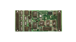
IP-512
Quad Isolated Serial I/O Industry Pack EIA-485
- ST16C554 Enhanced Controller
- Quad Synchronous Serial Ports
- 16/128-byte FIFO per Line (TX and RX)
- 1.5 Mbps transmit/receive operation (24MHz)
- Serial port independently isolated for high voltage
- Individual baud rate generators per port
- Software selectable Baud Rate Generator
- 230 Kbits Async, up to 2 Mbits Sync
- Full handshake control line
- Selectable socketed termination resistors
- Standard Modem Interface
Share this product
LinkedIn
IP-512
Quad Isolated Serial I/O Industry Pack EIA-485
The IP512-16-XX module is a quad-channel Serial Communication Controller featuring a 16-byte FIFO per line (optional 128-byte) with an error flag on the receive line. Based on the four-channel UARTs ST16C554/854, it includes larger FIFOs and provides four asynchronous ports supporting speeds up to 1.5Mbps. It features a software-programmable baud rate generator using an external oscillator with user-selectable frequency, internal loopback capability for onboard diagnostics, four selectable receive FIFO interrupt trigger levels, and standard modem interface capability.
Applications
Ideally suited to work with high speed modems and shared network environments, that require fast data processing time, the IP512-16-XX is found in:
- Process Control and Industrial Automation
- Precision Instrumentation
- Direct Digital Waveform Generation
- Software-Controlled Gain Adjustment
- Automatic Test Equipment
- Many other applications
IP interface
- Compatible with Industry Pack Bus specification
- Identification EEPROM
- 8/32 MHz clock
- 16 bit data
Operating: Environmental
- Operating temperature
Commercial: 0 to +70 °C
Optional: -25°C to +80°C - Non-operating: -40°C to 85 °C
- Airflow requirement: 0.5 CFM
- Humidity: 5 to 90% (non-condensing)
- Altitude: 0 to 10,000 ft
Mechanical: Environmental
- Size: Vita 4 Type 1 IP 1.8″ x 3.9″
- Power: +5, +12, -12 volts
- Vibration: 0.5G RMS 20-2000 Hz rand
- Shock: 20 G, 11 ms, 1⁄2 sine
- Weight: tbd
- MTBF: >250,000 hours
- Part Number: IP512-16-XX
4 Channel RS-422/RS-485 Module
XX Clock Desired for Baud Rate
Optional Accessories:
- Part Number: TB-50-HDR
50 pin terminal block and 1 meter flat ribbon cable - Part Number: CBL-50-HDR
50 pin, 1 meter flat ribbon cable, IDC header connector
- ST16C554 Enhanced Controller
- Quad Synchronous Serial Ports
- 16/128-byte FIFO per Line (TX and RX)
- 1.5 Mbps transmit/receive operation (24MHz)
- Serial port independently isolated for high voltage
- Individual baud rate generators per port
- Software selectable Baud Rate Generator
- 230 Kbits Async, up to 2 Mbits Sync
- Full handshake control line
- Selectable socketed termination resistors
- Standard Modem Interface
| Mechanical Interface | Switched Mezzanine Card (XMC) Interface confirming to ANSI/VITA 42.0-2008 (Auxiliary Standard) Standard single-width (149mm x 74mm) | |||||||||
| Electrical Interface | PCI Express x4 Link (Base Specification 2.1) compliant interface conforming to ANSI/VITA 42.3-2006 (PCI Express Protocol Layer Standard) | |||||||||
| PCI Express Switch | PI7C9X2G312GP (Pericom) | |||||||||
| PCI Express to PCI Bridge | XIO2001 (Texas Instruments) | |||||||||
| User configurable FPGA | TXMC639-10R: XC7K160T-2FBG676I (AMD) TXMC639-11R: XC7K325T-2FBG676I (AMD) | |||||||||
| SPI-Flash | MT25QL128 (Micron) 128 Mbit (contains TXMC639 FPGA BRD) or compatible; +3.3 V supply voltage | |||||||||
| DDR3 RAM | 2x MT41K256M16TW-107 (Micron) 256Meg x 32 bit | |||||||||
| Board Configuration Controller | LCMXO2-7000HC (Lattice) | |||||||||
| ADC | LTC2320 -16 (Analog Devices) | |||||||||
| DAC | AD5547BRUZ (Analog Devices) | |||||||||
| A/D Channels | TXMC639-10R: 8 Differential 16bit A/D Channels TXMC639-11R: 16 Differential 16bit A/D Channels Input Configuration per BCC Device: Input Voltage Ranges: Differental : ±20.57 V, ±10.28 V or ±5.14 V (Single-Ended: ±10.28 V, ±5.14 V or ±2.57 V) All analog inputs are connected via an impedance converter and a second operation amplifier for level adjustment and filtering to the differential ADC inputs. The -3 dB limit of this input stage is at approx. 8MHz | |||||||||
| D/A Channels | TXMC639-10R: 4 Single-Ended 16 Bit D/A Channels TXMC639-11R: 8 Single-Ended 16 Bit D/A Channels Output range configurable per D/A channel. Maximum single-ended Output Voltage – Vout: ±10 V Maximum Output Drive Current for each Output: 10 mA Maximum Capacitive Load for each Output: 1000 pF Typical Settling Time for a 10 mA / 1000 pF: < 1 µs | |||||||||
| Digital Front I/O Channels | 32 digital I/O Lines
| |||||||||
| Digital Rear I/O Channels | 64 direct FPGA I/O lines to P14 Rear I/O connector
4 MGT line to P16 Rear I/O connector
| |||||||||
| Front I/O | Front I/O Samtec – ERF8_050_01_L_D_RA_L_TR | |||||||||
| P14 Rear I/O | 64 pin Mezzanine Connector (Molex 71436-2864 or compatible) | |||||||||
| P16 Rear I/O | 114 pin Mezzanine Connector (Samtec – ASP-105885-01) | |||||||||
| Power Requirements 1) | Depends on FPGA design With TXMC639 Board Reference Design / without external load
| |||||||||
| Temperature Range | Operating: – 40 °C to + 85 °C Storage: – 55 °C to + 125 °C | |||||||||
| MTBF 1) | 157 000 h to 161 000 h | |||||||||
| Humidity | 5% – 95% non-condensing | |||||||||
| Weight | 140 g |
1) depends on variant, for further details see User Manual
TXMC639-10R
| 8x Analog In, 4x Analog Out, XC7K160T-2FBG676 Kintex™ 7 FPGA AMD Kintex™ 7 FPGA (XC7K160T-2FBG676), 1GB DDR3, 8x Analog In, 4x Analog Out, 32x digital Front I/O, 64x direct FPGA Rear I/O Lines and 4x MGTs Rear I/O |
TXMC639-11R
| 16x Analog In, 8x Analog Out, XC7K325T-2FBG676 Kintex™ 7 FPGA AMD Kintex™ 7 FPGA (XC7K325T-2FBG676), 1GB DDR3, 16x Analog In, 8x Analog Out, 32x digital Front I/O, 64x direct FPGA Rear I/O Lines and 4x MGTs Rear I/O |
SOFTWARE
Share this product
LinkedIn