Now Offering VITA 93 - QMC! Learn More >>

NOW OFFERING - VITA 93 - QMC!

PCie-Mini-CAN-FD

PCIe Mini CAN Controller – PCI Express x1

CAN Bus

  • Four channel CAN controller
  • Supports classic CAN and CAN FD
  • Complies with
    • ISO11898-1:2015
    • M_CAN Revision 3.2.1.1
  • Meets requirements of ISO11898-2:2016
  • Data rates from 40Kbps to 8Mbps
  • Software programmable speed selection

Share this product

LinkedIn

Got Questions?

PCie-Mini-CAN-FD

PCIe Mini CAN Controller – PCI Express x1

CAN Bus

  • Four channel CAN controller
  • Supports classic CAN and CAN FD
  • Complies with
    • ISO11898-1:2015
    • M_CAN Revision 3.2.1.1
  • Meets requirements of ISO11898-2:2016
  • Data rates from 40Kbps to 8Mbps
  • Software programmable speed selection

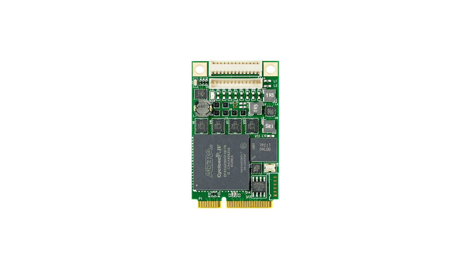
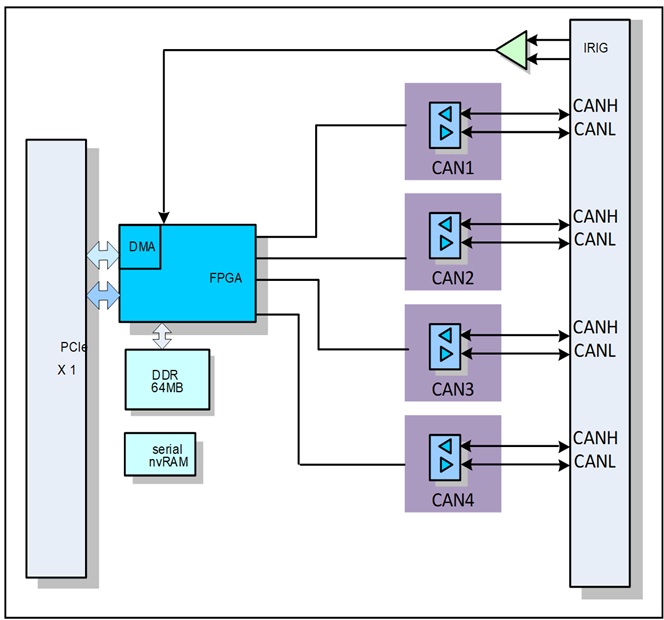
The PCIe-Mini-CAN-FD is PCIexpress controller with an integrated CAN FD transceiver supporting data rates up to 8 Mbps. The CAN FD controller meets the specifications of the ISO11898-1:2015 high speed controller area network (CAN) data link layer and meets the physical layer requirements of the ISO11898–2:2016 high speed CAN specification. The PCIe-Mini-CAN-FD provides an interface between the CAN bus and the system processor that support both classical CAN and CAN FD. The PCIe-Mini-CAN-FD provides CAN FD transceiver functionality – differential transmit-receive capability from the bus. It also supports local wake up (LWU) and bus wake up (WUP). The PCIe-Mini-CAN-FD device includes many protection features providing device and CAN bus robustness. These features include failsafe mode, internal dominant state timeout, wide bus operating range and a timeout watchdog as examples.

CAN Bus

  • Independent Software controlled
    • 120 Ohm Termination
    • Internal External Power Source
  • CAN bus robustness
    • ±42V bus fault protection
    • Failsafe mode
    • Internal dominant state timeout
    • Timeout watchdog
  • IRIG-B input
  • ±15KV ESD protection
  • PCI Express x1 interface

Applications

This board is optimally suited for communications gateway and protocol coveters. This is a perfect solution for:

  • Automotive
  • Avionics equipment
  • Avionic data communication systems
  • Medical systems
  • Industrial Transportation and controls

Available Software Drivers

  • Linux® SocketCAN drivers
  • Windows® drivers

Mechanical

  • Size: Mini PCIe Module
    30mm x 50.95mm
  • Power: tbd
  • Front panel I/O
  • Vibration: 0.5G, 20-2000Hz rand
  • Shock: 20G, 11ms, ½ sine
  • Weight: tbd
  • MTBF: >250,000 hours

Operating Environment

  • Operating temperature
    Commercial: 0 to +70ºC
    Industrial: -40ºC to +85ºC
  • Non-operating: -60ºC to +120ºC
  • Humidity: 5 to 90% (non-cond)
  • Altitude: 0 to 10,000 feet

Ordering information

PCIe-Mini–CAN-FD: Four-channels CAN Bus on Mini PCIe
PCIe-Mini–CAN-FD-I: Same as above with -40ºC to +85ºC

Optional Accessories

CBL-Mini-CANFD-12-OPEN: CAN Cable, 12 Inch Micro- Pigtail
CBL-Mini-CANFD-12-DB9: CAN Cable, 12 Inch Micro to DB9
Data Sheet – Link Here
Manual – Link Here

CAN Bus
  • Four channel CAN controller
  • Supports classic CAN and CAN FD
  • Complies with
    • ISO11898-1:2015
    • M_CAN Revision 3.2.1.1
  • Meets requirements of ISO11898-2:2016
  • Data rates from 40Kbps to 8Mbps
  • Software programmable speed selection


Mechanical Interface

Switched Mezzanine Card (XMC) Interface confirming to ANSI/VITA 42.0-2008 (Auxiliary Standard)

Standard single-width (149mm x 74mm)

Electrical InterfacePCI Express x4 Link (Base Specification 2.1) compliant interface conforming to ANSI/VITA 42.3-2006 (PCI Express Protocol Layer Standard)
PCI Express SwitchPI7C9X2G312GP (Pericom)
PCI Express to PCI BridgeXIO2001 (Texas Instruments)
User configurable FPGA

TXMC639-10R: XC7K160T-2FBG676I (AMD)

TXMC639-11R: XC7K325T-2FBG676I (AMD)

SPI-FlashMT25QL128 (Micron) 128 Mbit (contains TXMC639 FPGA BRD) or compatible; +3.3 V supply voltage
DDR3 RAM2x MT41K256M16TW-107 (Micron) 256Meg x 32 bit
Board Configuration ControllerLCMXO2-7000HC (Lattice)
ADCLTC2320 -16 (Analog Devices)
DACAD5547BRUZ (Analog Devices)
A/D Channels

TXMC639-10R: 8 Differential 16bit A/D Channels

TXMC639-11R: 16 Differential 16bit A/D Channels

Input Configuration per BCC Device:

Input Voltage Ranges:

Differental : ±20.57 V, ±10.28 V or ±5.14 V

(Single-Ended: ±10.28 V, ±5.14 V or ±2.57 V)

All analog inputs are connected via an impedance converter and a second operation amplifier for level adjustment and filtering to the differential ADC inputs.

The -3 dB limit of this input stage is at approx. 8MHz

D/A Channels

TXMC639-10R: 4 Single-Ended 16 Bit D/A Channels

TXMC639-11R: 8 Single-Ended 16 Bit D/A Channels

Output range configurable per D/A channel.
Simultaneous Conversion for all D/A Channels.

Maximum single-ended Output Voltage – Vout: ±10 V

Maximum Output Drive Current for each Output: 10 mA

Maximum Capacitive Load for each Output: 1000 pF

Typical Settling Time for a 10 mA / 1000 pF: < 1 µs

Digital Front I/O Channels

32 digital I/O Lines

  • Default configured as 32 ESD-protected TTL lines
  • 16 I/O lines are configurable as 8 differential RS422 I/O lines with individual Termination enable.
Digital Rear I/O Channels

64 direct FPGA I/O lines to P14 Rear I/O connector

  • Can be used as single-ended or differential I/O
  • FPGA I/O Standard: LVCMOS25, LVTTL25 and LVDS25

4 MGT line to P16 Rear I/O connector

  • Each line consists of one differential RX and TX pair.
  • Transmission speeds of up to 3.125 Gb/s are possible.
Front I/OFront I/O Samtec – ERF8_050_01_L_D_RA_L_TR
P14 Rear I/O64 pin Mezzanine Connector (Molex 71436-2864 or compatible)
P16 Rear I/O114 pin Mezzanine Connector (Samtec – ASP-105885-01)
Power Requirements 1)

Depends on FPGA design

With TXMC639 Board Reference Design / without external load

 typical @ +12 V VPWRtypical @ +5 V VPWR
TXMC639-10R1.1 A2.5 A
TXMC639-11R1.3 A3.3 A
Temperature RangeOperating: – 40 °C to + 85 °C
Storage: – 55 °C to + 125 °C
MTBF 1)157 000 h to 161 000 h
Humidity5% – 95% non-condensing
Weight140 g

1) depends on variant, for further details see User Manual


TXMC639-10R


8x Analog In, 4x Analog Out, XC7K160T-2FBG676 Kintex™ 7 FPGA

AMD Kintex™ 7 FPGA (XC7K160T-2FBG676), 1GB DDR3, 8x Analog In, 4x Analog Out, 32x digital Front I/O, 64x direct FPGA Rear I/O Lines and 4x MGTs Rear I/O

TXMC639-11R


16x Analog In, 8x Analog Out, XC7K325T-2FBG676 Kintex™ 7 FPGA

AMD Kintex™ 7 FPGA (XC7K325T-2FBG676), 1GB DDR3, 16x Analog In, 8x Analog Out, 32x digital Front I/O, 64x direct FPGA Rear I/O Lines and 4x MGTs Rear I/O

SOFTWARE

Device Driver for Board Family with Reconfigurable FPGA

Data Sheet – Link-Here

User Manual – Link-Here

Share this product

LinkedIn
Scroll to Top

User Manual Request

Please submit your information & we will send you a link and password to access our product manual. 

Please submit your information & we will send you a link and password to access our product manual. 

Already have a password? Visit manuals page below.

Already have a password?
Visit manuals page below.