- 16-bit D/A converter
- Settling time: 2 µsec, 0-5V range
- 500 KSPS throughput
- Six programmable output ranges per channel
- Up to 30 mA output drive
- Requires ±12V external power supply
- Unipolar: 0V to 5V, 0V to 10V
- Bipolar Mode: ±5V, ±10V, ±2.5V, –2.5V to 7.5V, ±10 mA continuous, ±30 mA max
- Multiple output spans available
- Temperature monitoring function
- Simultaneous or single update of D/A converter outputs
- Power-On Reset to 0V
- Two-stage buffers
- Global output buffer with internal or external triggering


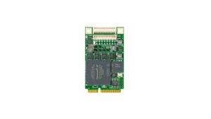
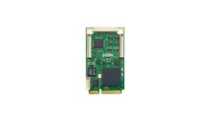
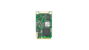
PCIe-Mini-DA4
4 Ch 16-bit D/A Software Programmable 2 µSecond DACs
- 16-bit D/A converter
- Settling time: 2 µsec, 0-5V range
- 500 KSPS throughput
- Six programmable output ranges per channel
- Up to 30 mA output drive
- Requires ±12V external power supply
- Unipolar: 0V to 5V, 0V to 10V
- Bipolar Mode: ±5V, ±10V, ±2.5V, –2.5V to 7.5V, ±10 mA continuous, ±30 mA max
- Multiple output spans available
- Temperature monitoring function
- Simultaneous or single update of D/A converter outputs
- Power-On Reset to 0V
- Two-stage buffers
- Global output buffer with internal or external triggering
Share this product
LinkedIn
PCIe-Mini-DA4
4 Ch 16-bit D/A Software Programmable 2 µSecond DACs
The PCIe-Mini-DA4 is a PCiexpress Mini board with a total of 4 voltage outputs D/A. Each output is followed by a buffer able to provide +/30 mA. Special function code allows global updates of all channels or by a group of eight channels at a time. Standard ping-pong output registers for each channel or optional data RAM allows waveform generation with minimum processor involvement.
An internal register sets the sampling rate of the internal sampling rate generator. The card operates in one of 3 modes:
- State machine providing automatic update and load on sampling clock.
- Manual load with update on sampling clock
- Manual load and update
Application:
This is a perfect solution for:
- Process control
- Industrial control
- Precision instrumentation
- Data acquisition systems (DAS)
- Multiaxis positioning systems
D/A Device Specifications:
- 16-bit, monotonic D/A converter
- Maximum 16-Bit INL Error: ±1 LSB over temperature
- 4 output channels per D/A A/D
- 2 μs settling time to ±1 LSB
- Low glitch impulse: 1 nV•s
- Program or pin-strap six output ranges
- Unipolar: 0V to 5V, 0V to 10V
- Bipolar: ±5V, ±10V, ±2.5V, –2.5V to 7.5V
- Power-On Reset to 0V
Mechanical: Environmental:
- Size: Mini PCIe Module (30 mm x 50.95 mm)
- Power: T.B.D.
- Front panel I/O
- Vibration: 0.5G, 20-2000 Hz random
- Shock: 20G, 11 msec, ½ sine
- Weight: T.B.D.
- MTBF: >250,000 hours
Operating Environment:
- Operating temperature: -40 ºC to +85 ºC
- Airflow requirement: 5 CFM
- Humidity: 5 to 90% (non-condensing)
- Altitude: 0 to 10,000 feet
Ordering Information:
- Part number: PCIe-Mini-DA4
- 4 Channels 16 Bits DA, Ext Temp: -40 ºC to +85 ºC
Data Sheet – Link Here
- 16-bit D/A converter
- Settling time: 2 µsec, 0-5V range
- 500 KSPS throughput
- Six programmable output ranges per channel
- Up to 30 mA output drive
- Requires ±12V external power supply
- Unipolar: 0V to 5V, 0V to 10V
- Bipolar Mode: ±5V, ±10V, ±2.5V, –2.5V to 7.5V, ±10 mA continuous, ±30 mA max
- Multiple output spans available
- Temperature monitoring function
- Simultaneous or single update of D/A converter outputs
- Power-On Reset to 0V
- Two-stage buffers
- Global output buffer with internal or external triggering
| Mechanical Interface | Switched Mezzanine Card (XMC) Interface confirming to ANSI/VITA 42.0-2008 (Auxiliary Standard) Standard single-width (149mm x 74mm) | |||||||||
| Electrical Interface | PCI Express x4 Link (Base Specification 2.1) compliant interface conforming to ANSI/VITA 42.3-2006 (PCI Express Protocol Layer Standard) | |||||||||
| PCI Express Switch | PI7C9X2G312GP (Pericom) | |||||||||
| PCI Express to PCI Bridge | XIO2001 (Texas Instruments) | |||||||||
| User configurable FPGA | TXMC639-10R: XC7K160T-2FBG676I (AMD) TXMC639-11R: XC7K325T-2FBG676I (AMD) | |||||||||
| SPI-Flash | MT25QL128 (Micron) 128 Mbit (contains TXMC639 FPGA BRD) or compatible; +3.3 V supply voltage | |||||||||
| DDR3 RAM | 2x MT41K256M16TW-107 (Micron) 256Meg x 32 bit | |||||||||
| Board Configuration Controller | LCMXO2-7000HC (Lattice) | |||||||||
| ADC | LTC2320 -16 (Analog Devices) | |||||||||
| DAC | AD5547BRUZ (Analog Devices) | |||||||||
| A/D Channels | TXMC639-10R: 8 Differential 16bit A/D Channels TXMC639-11R: 16 Differential 16bit A/D Channels Input Configuration per BCC Device: Input Voltage Ranges: Differental : ±20.57 V, ±10.28 V or ±5.14 V (Single-Ended: ±10.28 V, ±5.14 V or ±2.57 V) All analog inputs are connected via an impedance converter and a second operation amplifier for level adjustment and filtering to the differential ADC inputs. The -3 dB limit of this input stage is at approx. 8MHz | |||||||||
| D/A Channels | TXMC639-10R: 4 Single-Ended 16 Bit D/A Channels TXMC639-11R: 8 Single-Ended 16 Bit D/A Channels Output range configurable per D/A channel. Maximum single-ended Output Voltage – Vout: ±10 V Maximum Output Drive Current for each Output: 10 mA Maximum Capacitive Load for each Output: 1000 pF Typical Settling Time for a 10 mA / 1000 pF: < 1 µs | |||||||||
| Digital Front I/O Channels | 32 digital I/O Lines
| |||||||||
| Digital Rear I/O Channels | 64 direct FPGA I/O lines to P14 Rear I/O connector
4 MGT line to P16 Rear I/O connector
| |||||||||
| Front I/O | Front I/O Samtec – ERF8_050_01_L_D_RA_L_TR | |||||||||
| P14 Rear I/O | 64 pin Mezzanine Connector (Molex 71436-2864 or compatible) | |||||||||
| P16 Rear I/O | 114 pin Mezzanine Connector (Samtec – ASP-105885-01) | |||||||||
| Power Requirements 1) | Depends on FPGA design With TXMC639 Board Reference Design / without external load
| |||||||||
| Temperature Range | Operating: – 40 °C to + 85 °C Storage: – 55 °C to + 125 °C | |||||||||
| MTBF 1) | 157 000 h to 161 000 h | |||||||||
| Humidity | 5% – 95% non-condensing | |||||||||
| Weight | 140 g |
1) depends on variant, for further details see User Manual
TXMC639-10R
| 8x Analog In, 4x Analog Out, XC7K160T-2FBG676 Kintex™ 7 FPGA AMD Kintex™ 7 FPGA (XC7K160T-2FBG676), 1GB DDR3, 8x Analog In, 4x Analog Out, 32x digital Front I/O, 64x direct FPGA Rear I/O Lines and 4x MGTs Rear I/O |
TXMC639-11R
| 16x Analog In, 8x Analog Out, XC7K325T-2FBG676 Kintex™ 7 FPGA AMD Kintex™ 7 FPGA (XC7K325T-2FBG676), 1GB DDR3, 16x Analog In, 8x Analog Out, 32x digital Front I/O, 64x direct FPGA Rear I/O Lines and 4x MGTs Rear I/O |
SOFTWARE
Share this product
LinkedIn