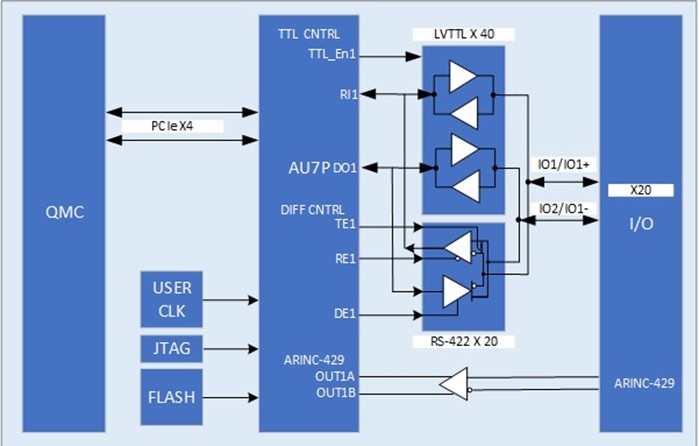
- QMC PCI Express x4 lane interface
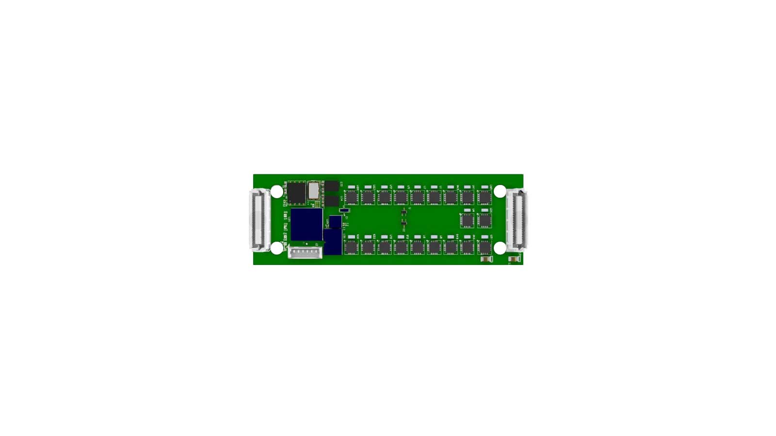
- QMC 26mm x 78.25 mm
- User-reconfigurable AMD-Xilinx Artix UltraScale+ FPGA
- Up to 20 Pairs RS-422/485 bidirectional channels, 20Mb/s data rate per channel, software-selectable half or full duplex, or Up to 40 Channels LVTTL
- Software-selectable 120Ω termination
- Software-programmable interrupts for Change-of-State/Level detection
- High Precision User Clock PPB Input on Board
- Optional ARINC-429 Receiver
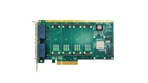
QMC-XCAU7P
QMC PCIe x4 User Reconfigurable AMD-XILINX ARTIX ULTRASCALE+ FPGA 20 Channels RS-422/485 OR 40 Channels LVTTL
- QMC PCI Express x4 lane interface
- QMC 26mm x 78.25 mm
- User-reconfigurable AMD-Xilinx Artix UltraScale+ FPGA
- Up to 20 Pairs RS-422/485 bidirectional channels, 20Mb/s data rate per channel, software-selectable half or full duplex, or Up to 40 Channels LVTTL
- Software-selectable 120Ω termination
- Software-programmable interrupts for Change-of-State/Level detection
- High Precision User Clock PPB Input on Board
- Optional ARINC-429 Receiver
Share this product
LinkedIn
QMC-XCAU7P
QMC PCIe x4 User Reconfigurable AMD-XILINX ARTIX ULTRASCALE+ FPGA 20 Channels RS-422/485 OR 40 Channels LVTTL
The QMC-XCAU7P-FPGA has 40 I/O channels that can monitor or control the on/off (high/low) status of up to 20 differential devices or up to 40 channels LVTTL, software selectable in groups of 2. Each channel can be used as an input or output. The Input channels can be configured with interrupts to detect a change of state, or level detection of any bit. The RS-422/485 input threshold includes hysteresis for increased noise immunity.
Applications
- Process control
- Industrial control
- Precision instrumentation
- Data acquisition systems (DAS)
- Multiaxis positioning systems
Digital I/O Specifications
- Up to 20 channel pairs RS-422/485, or Up to 40 channels LVTTL
- 20Mb/s data rate per RS422/485 channel
- Optional High Precision PPB User Clock
- Half or full duplex and 120Ω on-board termination, software-selectable
- High input impedance supports 256 nodes
- Enhanced ESD protection to ±25kV
Available Software Drivers
- C library dll’s
- Linux® drivers
- Windows® drivers
- VxWorks® drivers
Mechanical
- Size: QMC Module (26mm x 78.25 mm)
- Power: 240mA
- Vibration: 0.5G, 20-2000Hz rand
- Shock: 20G, 11ms, ½ sine
- Weight: 10g (0.4oz)
- MTBF: >250,000 hours
Operating Environment
- Operating temperature Industrial: -40ºC to +85ºC
- Airflow requirement: 5CFM
- Humidity: 5 to 90% (non-cond)
- Altitude: 0 to 10,000 feet
Ordering Information
- QMC-XCAU7P-FPGA : 20 Channels differential RS-422/485 or 40 LVTTL, Industrial Temp: -40ºC to +85ºC
- QMC-XCAU7P-FPGA-1 : 20 Channels differential RS-422/485 or 40 LVTTL, 1 Ch RX ARINC-429, High Precision 50MHz Clock Input, Industrial Temp: -40ºC to +85ºC
Data Sheet – Link Here
- QMC PCI Express x4 lane interface
- QMC 26mm x 78.25 mm
- User-reconfigurable AMD-Xilinx Artix UltraScale+ FPGA
- Up to 20 Pairs RS-422/485 bidirectional channels, 20Mb/s data rate per channel, software-selectable half or full duplex, or Up to 40 Channels LVTTL
- Software-selectable 120Ω termination
- Software-programmable interrupts for Change-of-State/Level detection
- High Precision User Clock PPB Input on Board
- Optional ARINC-429 Receiver
| Mechanical Interface | Switched Mezzanine Card (XMC) Interface confirming to ANSI/VITA 42.0-2008 (Auxiliary Standard) Standard single-width (149mm x 74mm) | |||||||||
| Electrical Interface | PCI Express x4 Link (Base Specification 2.1) compliant interface conforming to ANSI/VITA 42.3-2006 (PCI Express Protocol Layer Standard) | |||||||||
| PCI Express Switch | PI7C9X2G312GP (Pericom) | |||||||||
| PCI Express to PCI Bridge | XIO2001 (Texas Instruments) | |||||||||
| User configurable FPGA | TXMC639-10R: XC7K160T-2FBG676I (AMD) TXMC639-11R: XC7K325T-2FBG676I (AMD) | |||||||||
| SPI-Flash | MT25QL128 (Micron) 128 Mbit (contains TXMC639 FPGA BRD) or compatible; +3.3 V supply voltage | |||||||||
| DDR3 RAM | 2x MT41K256M16TW-107 (Micron) 256Meg x 32 bit | |||||||||
| Board Configuration Controller | LCMXO2-7000HC (Lattice) | |||||||||
| ADC | LTC2320 -16 (Analog Devices) | |||||||||
| DAC | AD5547BRUZ (Analog Devices) | |||||||||
| A/D Channels | TXMC639-10R: 8 Differential 16bit A/D Channels TXMC639-11R: 16 Differential 16bit A/D Channels Input Configuration per BCC Device: Input Voltage Ranges: Differental : ±20.57 V, ±10.28 V or ±5.14 V (Single-Ended: ±10.28 V, ±5.14 V or ±2.57 V) All analog inputs are connected via an impedance converter and a second operation amplifier for level adjustment and filtering to the differential ADC inputs. The -3 dB limit of this input stage is at approx. 8MHz | |||||||||
| D/A Channels | TXMC639-10R: 4 Single-Ended 16 Bit D/A Channels TXMC639-11R: 8 Single-Ended 16 Bit D/A Channels Output range configurable per D/A channel. Maximum single-ended Output Voltage – Vout: ±10 V Maximum Output Drive Current for each Output: 10 mA Maximum Capacitive Load for each Output: 1000 pF Typical Settling Time for a 10 mA / 1000 pF: < 1 µs | |||||||||
| Digital Front I/O Channels | 32 digital I/O Lines
| |||||||||
| Digital Rear I/O Channels | 64 direct FPGA I/O lines to P14 Rear I/O connector
4 MGT line to P16 Rear I/O connector
| |||||||||
| Front I/O | Front I/O Samtec – ERF8_050_01_L_D_RA_L_TR | |||||||||
| P14 Rear I/O | 64 pin Mezzanine Connector (Molex 71436-2864 or compatible) | |||||||||
| P16 Rear I/O | 114 pin Mezzanine Connector (Samtec – ASP-105885-01) | |||||||||
| Power Requirements 1) | Depends on FPGA design With TXMC639 Board Reference Design / without external load
| |||||||||
| Temperature Range | Operating: – 40 °C to + 85 °C Storage: – 55 °C to + 125 °C | |||||||||
| MTBF 1) | 157 000 h to 161 000 h | |||||||||
| Humidity | 5% – 95% non-condensing | |||||||||
| Weight | 140 g |
1) depends on variant, for further details see User Manual
TXMC639-10R
| 8x Analog In, 4x Analog Out, XC7K160T-2FBG676 Kintex™ 7 FPGA AMD Kintex™ 7 FPGA (XC7K160T-2FBG676), 1GB DDR3, 8x Analog In, 4x Analog Out, 32x digital Front I/O, 64x direct FPGA Rear I/O Lines and 4x MGTs Rear I/O |
TXMC639-11R
| 16x Analog In, 8x Analog Out, XC7K325T-2FBG676 Kintex™ 7 FPGA AMD Kintex™ 7 FPGA (XC7K325T-2FBG676), 1GB DDR3, 16x Analog In, 8x Analog Out, 32x digital Front I/O, 64x direct FPGA Rear I/O Lines and 4x MGTs Rear I/O |
SOFTWARE
Share this product
LinkedIn