- 16-bit Resolver-to-Digital Converter
- Programmable features
- Resolution: 10, 12, 14, or 16 bits
- Accuracy up to 1 Arc Minute
- Bandwidth: DC to 10KHz
- Velocity output scaling and encoder emulation
- Synchro input option 11.8V or 90V
- On board excitation
- Four Channels, 16-bit SoftSpan™ DAC
- Programmable output ranges ±10V
- 10μs settling time
- 30mA output drive
PCIe-Mini-SYNCHRO
16-bit Synchro/Resolver w/Four Channels, 16 bits D/A
- 16-bit Resolver-to-Digital Converter
- Programmable features
- Resolution: 10, 12, 14, or 16 bits
- Accuracy up to 1 Arc Minute
- Bandwidth: DC to 10KHz
- Velocity output scaling and encoder emulation
- Synchro input option 11.8V or 90V
- On board excitation
- Four Channels, 16-bit SoftSpan™ DAC
- Programmable output ranges ±10V
- 10μs settling time
- 30mA output drive
Share this product
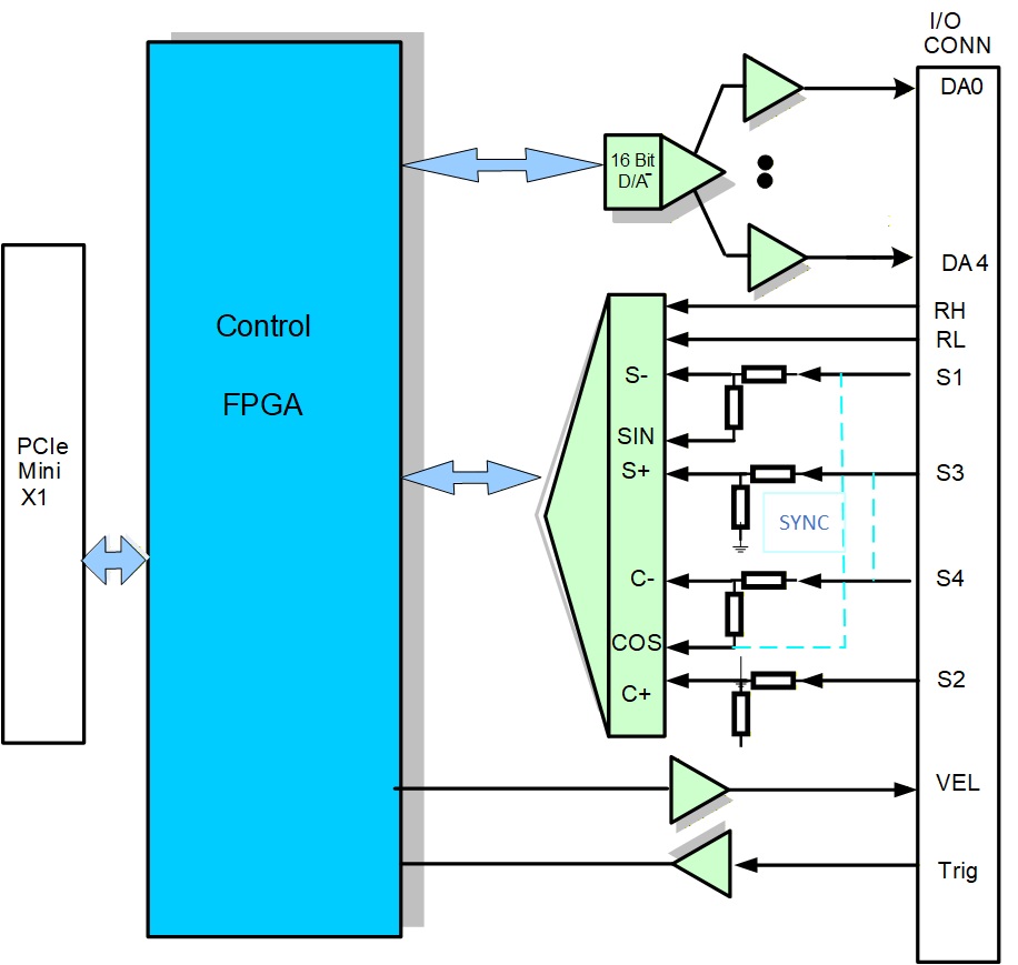
The PCIe-Mini-SYNCHRO module is a one channel Synchro/Resolver controller. It uses a state of the art 16-bit monolithic Resolver-to-Digital converter. This single chip converter offers programmable features such as resolution, bandwidth, velocity output scaling and encoder emulation. Resolution programming allows selection of 10, 12, 14, or 16 bits, with accuracies to 1 Arc Minute. The internal Synthesized Reference feature eliminates errors due to quadrature voltage and ensures operation with a rotor-to-stator phase shift of up to 45 degrees. The velocity output (VEL) can be used in place of a tachometer. This converter provides the option of using a second set of filter components, which can be used in dual bandwidth or switch on the fly applications. This module also has four channels, 16-bit DAC with 10μs settling time and ±10V outputs.
Synchro Resolver capabilities
- Accuracy up to 1 Arc Minute
- Used to Interpolate Synchro, Resolver, Inductosyn, LVDT, RVDT, and Hall sensors
- DC to 10KHz
- Internal synthesized reference
- Programmable resolution, dual bandwidth, and tracking rate
- Internal encoder emulation with independent resolution control
- Velocity output eliminates tachometer
- Built-In-Test (BIT) output, no 180° hang-up with AC Reference
- The RDC channels can have several different input configurations:
- Direct
- Differential
- Resolver
- Synchro
- With 16 Bits Resolution:
- Tracking rate of 18 RPS
- Bandwidth 300Hz
- Acceleration constant Ka of 360K 1/sec²
- Settling time 50ms
Digital to Analog capabilities
- Four Channels DAC
- 16-Bit Resolution
- 10μs settling time
- Buffered Voltage Output
- 30mA drive per Channel
Applications
Applications include antenna positioning, scientific, laboratory, medical and machine control.
Available Software Drivers
- Linux® drivers
- Windows® drivers
- VxWorks® drivers
Mechanical
- Size: Mini PCIe Module
(30mm x 50.95mm) - Power: 240mA
- Front panel I/O
- Vibration: 0.5G, 20-2000Hz rand
- Shock: 20G, 11ms, ½ sine
- Weight: 10g (0.4oz)
- MTBF: >250,000 hours
Operating Environment
- Operating temperature
Commercial: 0 to +70ºC
Industrial: -40ºC to +85ºC - Non-operating: -50ºC to +90ºC
- Airflow requirement: .5CFM
- Humidity: 5 to 90% (non-cond)
- Altitude: 0 to 10,000 feet
Ordering information
PCIe-Mini-SYNCHRO-1S One Channel Synchro 11.8V, Industrial Temp -40ºC to +85ºC
PCIe-Mini-SYNCHRO-1R One Channel Resolver 11.8V, Industrial Temp -40ºC to +85ºC
PCIe-Mini-SYNCHRO-2S One Channel Synchro 90V, Industrial Temp -40ºC to +85ºC
PCIe-Mini-SYNCHRO-2R One Channel Resolver 90V, Industrial Temp -40ºC to +85ºC
Append -CC for Conformal Coat
Optional Accessories
CBL-SYNCHRO-12 13 pin pigtail Cable, 12in length
Data Sheet – Link Here
- 16-bit Resolver-to-Digital Converter
- Programmable features
- Resolution: 10, 12, 14, or 16 bits
- Accuracy up to 1 Arc Minute
- Bandwidth: DC to 10KHz
- Velocity output scaling and encoder emulation
- Synchro input option 11.8V or 90V
- On board excitation
- Four Channels, 16-bit SoftSpan™ DAC
- Programmable output ranges ±10V
- 10μs settling time
- 30mA output drive
| Mechanical Interface | Switched Mezzanine Card (XMC) Interface confirming to ANSI/VITA 42.0-2008 (Auxiliary Standard) Standard single-width (149mm x 74mm) | |||||||||
| Electrical Interface | PCI Express x4 Link (Base Specification 2.1) compliant interface conforming to ANSI/VITA 42.3-2006 (PCI Express Protocol Layer Standard) | |||||||||
| PCI Express Switch | PI7C9X2G312GP (Pericom) | |||||||||
| PCI Express to PCI Bridge | XIO2001 (Texas Instruments) | |||||||||
| User configurable FPGA | TXMC639-10R: XC7K160T-2FBG676I (AMD) TXMC639-11R: XC7K325T-2FBG676I (AMD) | |||||||||
| SPI-Flash | MT25QL128 (Micron) 128 Mbit (contains TXMC639 FPGA BRD) or compatible; +3.3 V supply voltage | |||||||||
| DDR3 RAM | 2x MT41K256M16TW-107 (Micron) 256Meg x 32 bit | |||||||||
| Board Configuration Controller | LCMXO2-7000HC (Lattice) | |||||||||
| ADC | LTC2320 -16 (Analog Devices) | |||||||||
| DAC | AD5547BRUZ (Analog Devices) | |||||||||
| A/D Channels | TXMC639-10R: 8 Differential 16bit A/D Channels TXMC639-11R: 16 Differential 16bit A/D Channels Input Configuration per BCC Device: Input Voltage Ranges: Differental : ±20.57 V, ±10.28 V or ±5.14 V (Single-Ended: ±10.28 V, ±5.14 V or ±2.57 V) All analog inputs are connected via an impedance converter and a second operation amplifier for level adjustment and filtering to the differential ADC inputs. The -3 dB limit of this input stage is at approx. 8MHz | |||||||||
| D/A Channels | TXMC639-10R: 4 Single-Ended 16 Bit D/A Channels TXMC639-11R: 8 Single-Ended 16 Bit D/A Channels Output range configurable per D/A channel. Maximum single-ended Output Voltage – Vout: ±10 V Maximum Output Drive Current for each Output: 10 mA Maximum Capacitive Load for each Output: 1000 pF Typical Settling Time for a 10 mA / 1000 pF: < 1 µs | |||||||||
| Digital Front I/O Channels | 32 digital I/O Lines
| |||||||||
| Digital Rear I/O Channels | 64 direct FPGA I/O lines to P14 Rear I/O connector
4 MGT line to P16 Rear I/O connector
| |||||||||
| Front I/O | Front I/O Samtec – ERF8_050_01_L_D_RA_L_TR | |||||||||
| P14 Rear I/O | 64 pin Mezzanine Connector (Molex 71436-2864 or compatible) | |||||||||
| P16 Rear I/O | 114 pin Mezzanine Connector (Samtec – ASP-105885-01) | |||||||||
| Power Requirements 1) | Depends on FPGA design With TXMC639 Board Reference Design / without external load
| |||||||||
| Temperature Range | Operating: – 40 °C to + 85 °C Storage: – 55 °C to + 125 °C | |||||||||
| MTBF 1) | 157 000 h to 161 000 h | |||||||||
| Humidity | 5% – 95% non-condensing | |||||||||
| Weight | 140 g |
1) depends on variant, for further details see User Manual
TXMC639-10R
| 8x Analog In, 4x Analog Out, XC7K160T-2FBG676 Kintex™ 7 FPGA AMD Kintex™ 7 FPGA (XC7K160T-2FBG676), 1GB DDR3, 8x Analog In, 4x Analog Out, 32x digital Front I/O, 64x direct FPGA Rear I/O Lines and 4x MGTs Rear I/O |
TXMC639-11R
| 16x Analog In, 8x Analog Out, XC7K325T-2FBG676 Kintex™ 7 FPGA AMD Kintex™ 7 FPGA (XC7K325T-2FBG676), 1GB DDR3, 16x Analog In, 8x Analog Out, 32x digital Front I/O, 64x direct FPGA Rear I/O Lines and 4x MGTs Rear I/O |